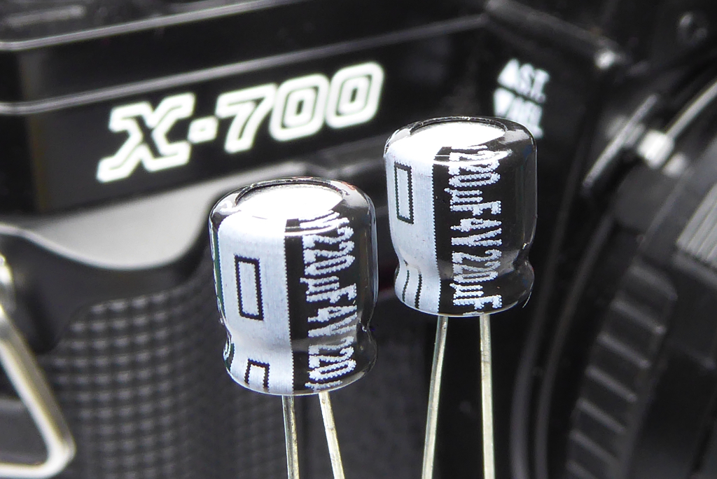
A step by step guide to Minolta X-700 capacitor replacement in the popular 35mm SLR Camera.
Copyright 2023 High5Cameras,
Free to use, copy and distribute so long as no charge is made for use,
distribution or access and authorship and web address is freely acknowledged.
The Minolta X-700 is one of the most popular cameras for modern film fans being equally at home in the hands of both the expert and novice photographer.
It can though suffer the dreaded capacitor-itis where its shutter release and aperture control capacitors can fail. If your camera has a serial number lower than 2000000 then it almost certainly has tantalum capacitors (STEC) and these are unlikely to be the cause of problems. Serial numbers higher than 2000000 usually have electrolytic capacitors (ALEC) and these are very often the culprits when problems arise.
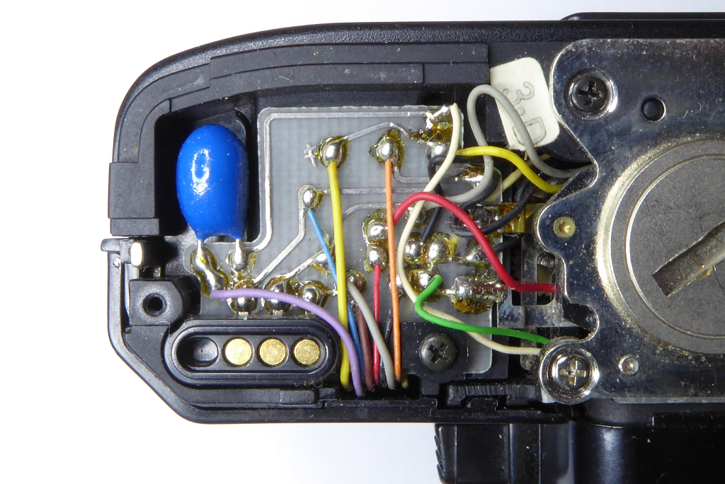
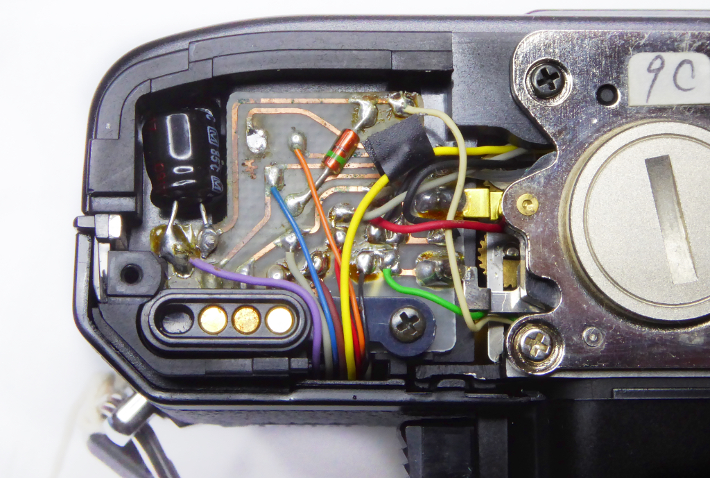
Serial numbers alone are not the best test. We have seen an X-700 in the 2040000 range with tantalum capacitors. The surest way to know for sure if your camera has the early tantalum bead type or the later electrolytic type is to remove the base plate and have a look. The pictures above show the two types of Minolta X-700 capacitor in use.
The classic symptom of Minolta X-700 capacitor failure is when you half press the shutter release the LEDs in the viewfinder will illuminate, on full press the LEDs will go out but the shutter will not activate. The winder/film advance will be locked solid because the shutter is wound on but the camera is unable to release the shutter.
Sometimes after a power down and power back up again the problem will clear but it will return after a few shots.
While this symptom is almost always related to capacitors it is not ALWAYS the case. Other faults can create these symptoms like shutter derails, jammed curtains, faulty release magnet and power issues to name a few. However if the symptoms arise it is usually best to consider capacitor replacement as the first step IF the camera has the electrolytic type capacitors and if you have made sure its not as simple as a corroded battery chamber or flat battery.
The X-700 is cursed with two capacitors which can be problematic – both are are 220uF 4V types. The good news is that modern ALEC capacitors are very long lasting and relatively inexpensive. You will need the smallest physical size you can get to ensure a good fit. Normally we fit using a Panasonic made capacitor with dimensions of 7.15mm long by 6.38mm wide.
This guide will hopefully get you through a Minolta X-700 capacitor replacement but do not over-estimate your soldering skills. The circuit boards in these cameras are VERY fragile and we have seen a fair few written off due to shoddy soldering work.
You will need the following tools and parts to replace a Minolta X-700 Capacitor
You will also need a great deal of patience coupled with a steady hand. I always use leaded solder with an internal flux core which works best. Lead free solder can be tricky to use and usually requires flux to make it work well.
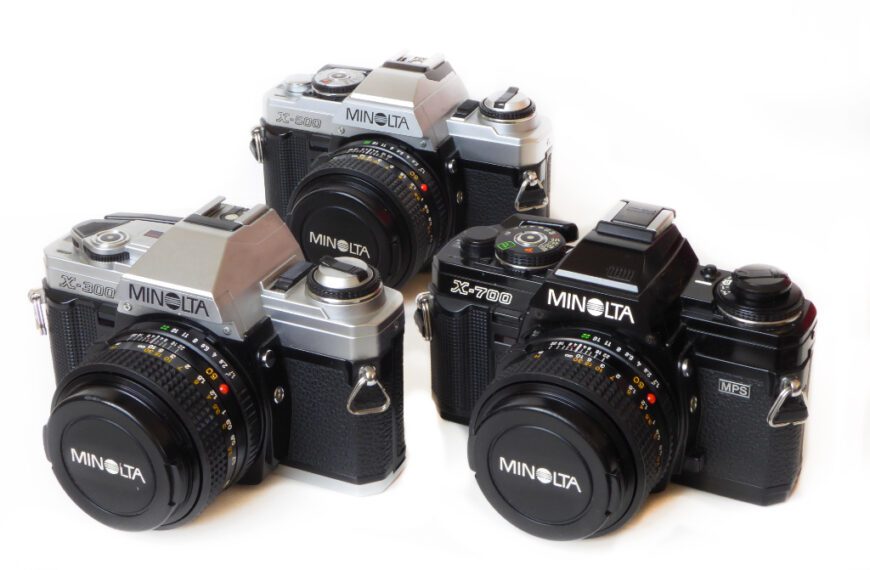
NOTES: This Minolta X-700 capacitor replacement guide can be used to replace the single capacitor in the base of X-500 and X-300 variants as well. Be aware though that the capacitors orientation is different. You need to check carefully which side the capacitor has its white (-) stripe prior to removal and make sure replacement is identical.
Note also that for this guide I am using a junk camera. Your soldering should be neater but its tough to photograph a process while working at your best single handed.
Read the Minolta x-700 capacitor replacement guide from start to finish before jumping in. As ever any repair is down to your tools and skills. Take you time, don’t rush. There are no prizes being offered for fastest repair times.
Minolta X-700 Capacitor Replacement – The Shutter Release Capacitor
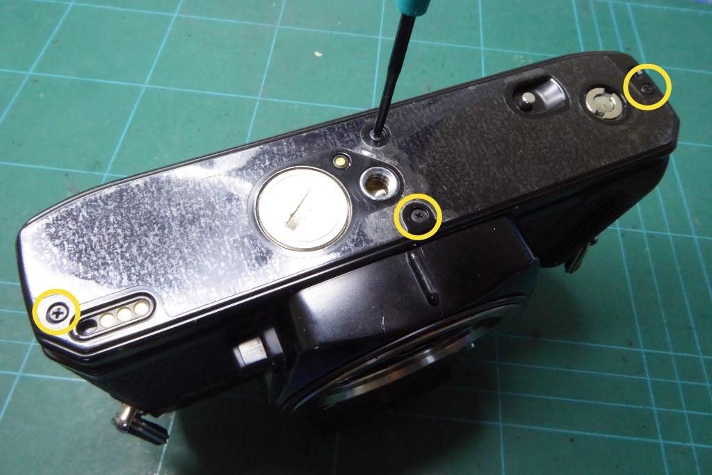
First step is to remove the base plate. It’s also sensible to remove the battery cap and batteries while work is being carried out.
Note that the two centre screws are much shorter than the two screws at the outer edges.
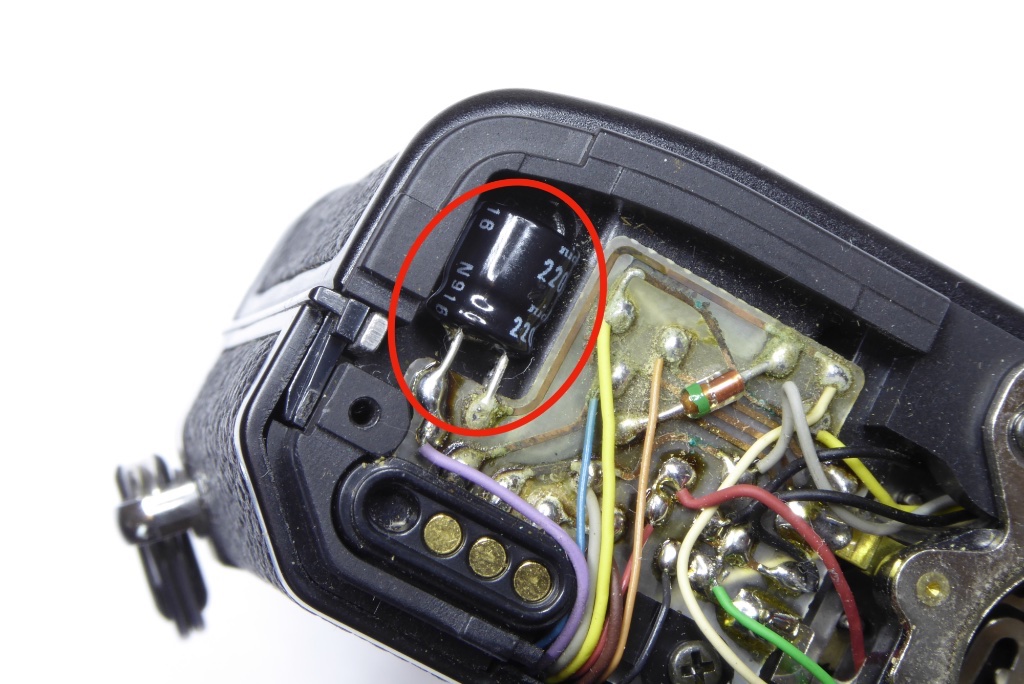
With the base removed observe the capacitor. If it looks like this is an ALEC type. Note the orientation of the white/grey stripe along one side. This is the negative (-) side of the capacitor and must be orientated correctly when replacing.
On an X-700 the stripe faces inwards and is nearest the circuit board. On an X-300 the stripe faces outwards towards the edge of the camera. You should make a note prior to removal.
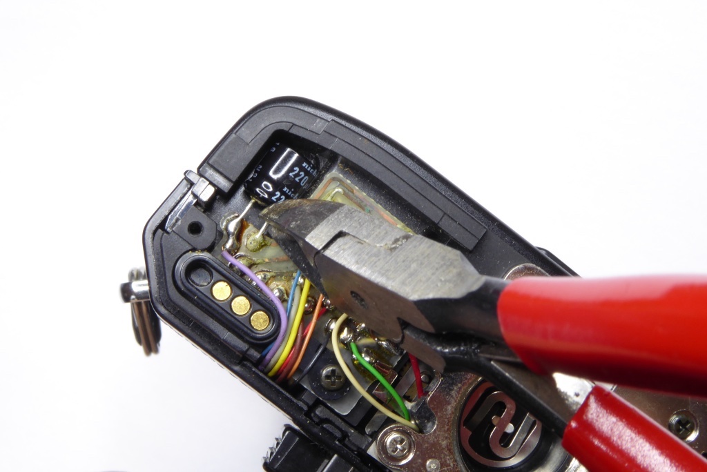
The circuit board in all versions of the X-700, X-500 and X-300 is very fragile. You need to minimise heat as the tracks and the board will simply burn away if too much heat is used.
The easiest way to remove the old capacitor is to clip it away from its leads with some snips.
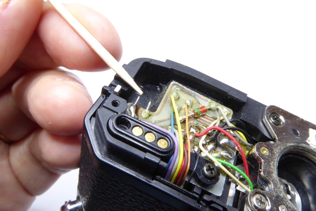
If you are nervous about applying heat to he circuit board you can now use the remains of the legs to solder the replacement onto…
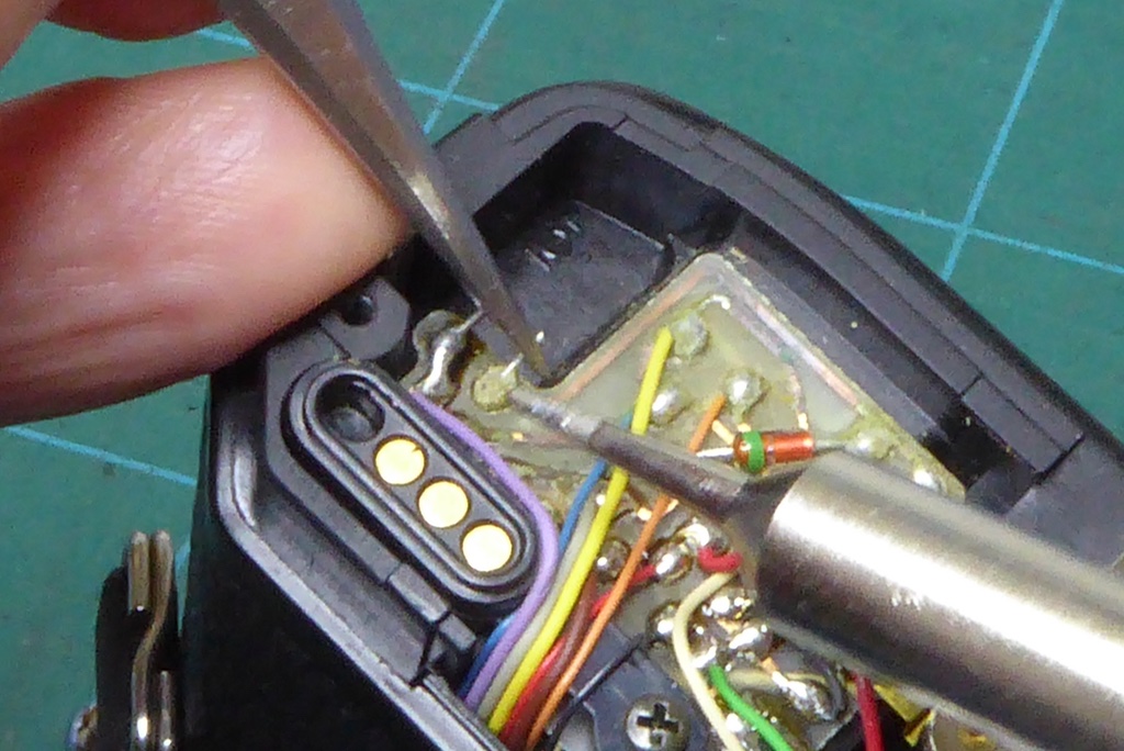
…Or simply desolder these. A light touch is needed.
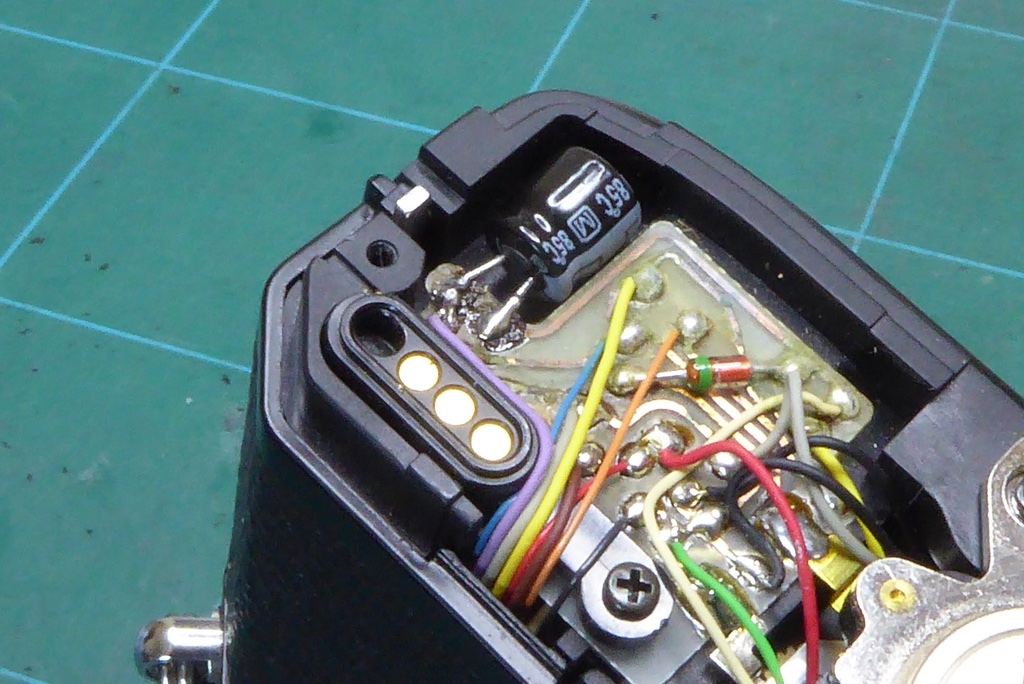
A replacement 220uf 4V Panasonic ALEC is now installed. You need to tin the leads on the capacitor and clip the legs to the right length. Some snipe nosed pliers are used to form the legs to the right distance apart.
If you are working on an X-300 or X-500 this completes the repair. Simply replace the base plate and test the camera.
Sometimes after capacitor replacement you may find your X-700 still refuses to fire. This can be because the upper aperture control capacitor is also defective but normally I make a small modification to the camera here as sometimes even with perfectly working capacitors the X-700 can fail to release the shutter.
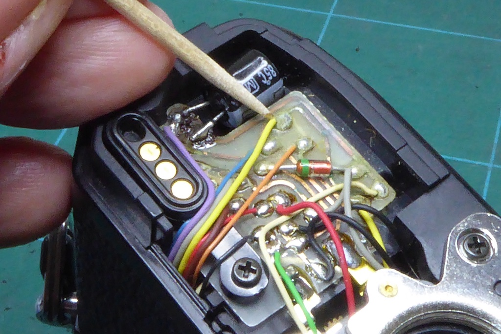
Note the yellow wire here and desolder this from the board.
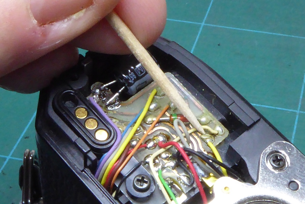
Note the other yellow wire leading onto the board here and desolder this from the board as well.
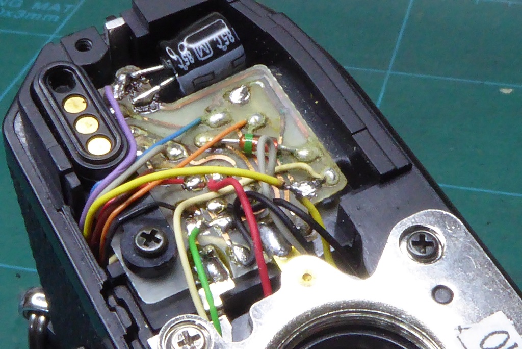
Solder the two yellow wires together like so and wrap a strip of insulation tape around them to prevent contact with the board.
CREDIT: to James Holman of Learn Camera Repair for this tip. It really does work and saves a lot of grief.
NOTE: It’s not a great pic – the two wires are not on the board they are simply soldered together end to end.
Minolta X-700 Capacitor Replacement – The Aperture Control Capacitor
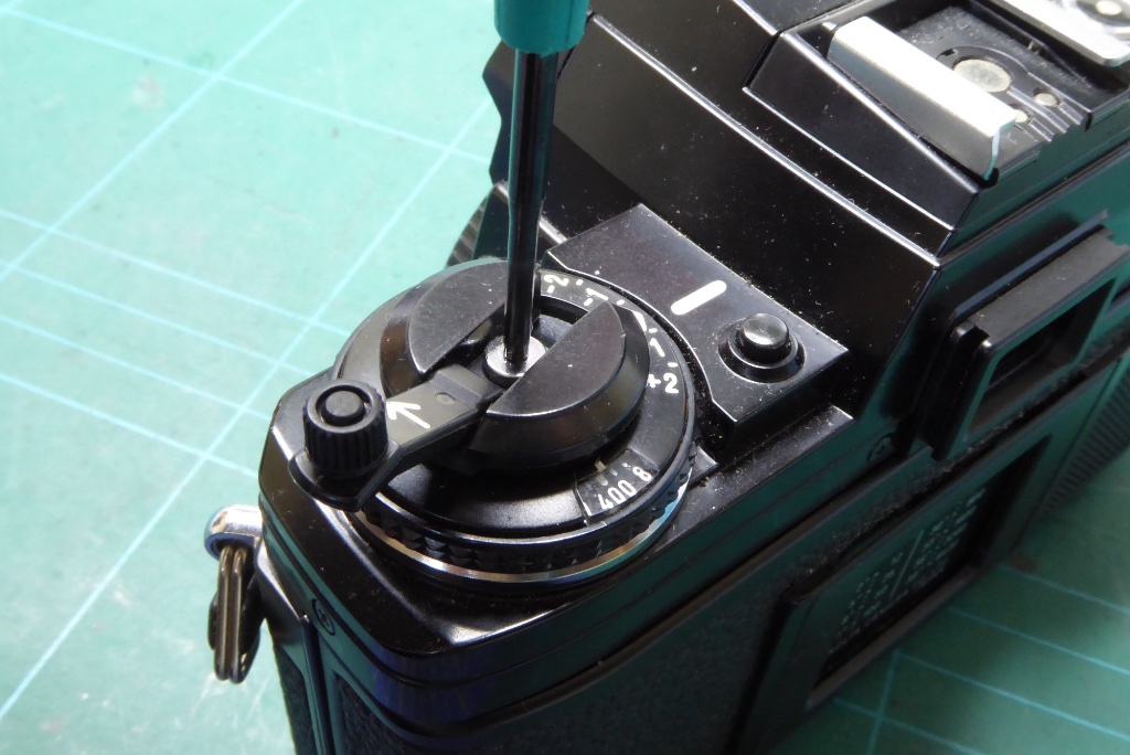
To get to the top capacitor which manages aperture control we need to remove the top cover. Only an X-700 has this capacitor the X-300 and X-500 do not support program mode so do not have an aperture control circuit.
Start by using a JIS screwdriver to remove the screw on top of the rewind capstan.
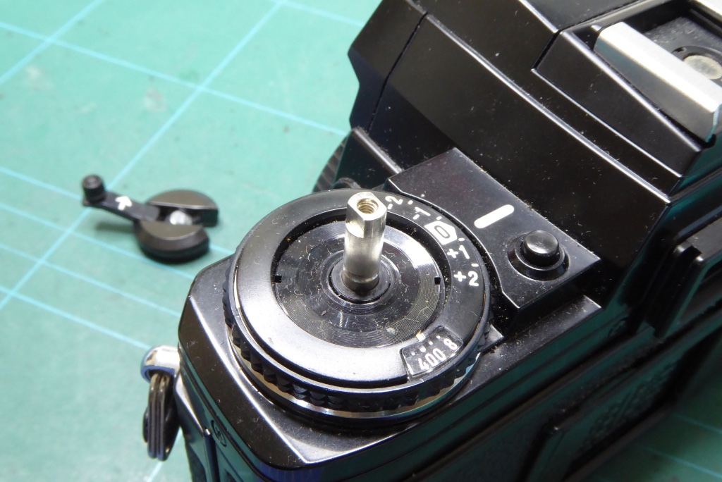
With the screw removed I usually put a strip of tape around the top of the film spool spindle. This will reduce the risk of it getting pushed into the camera and causing problems.
Set the ASA ring to a known value and make a note and set exposure compensation at Zero (0) this will make life a bit easier later.
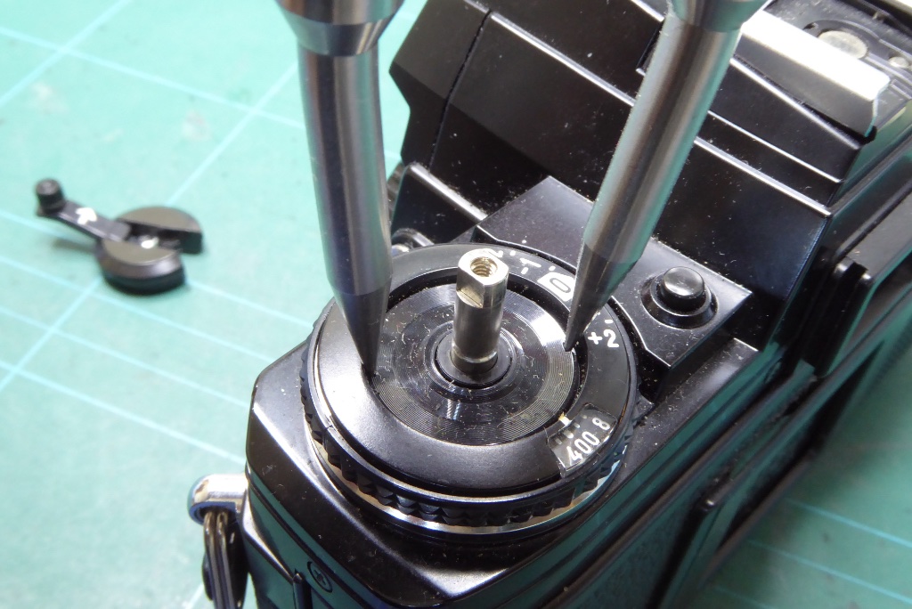
Use either a spanning wrench or a rubber bung to remove the slotted retaining ring underneath. On some X-700s this will be plastic but some have a metal retainer here. This is not generally very tight and a suitable rubber bung will usually remove this, it’s a conventional thread.
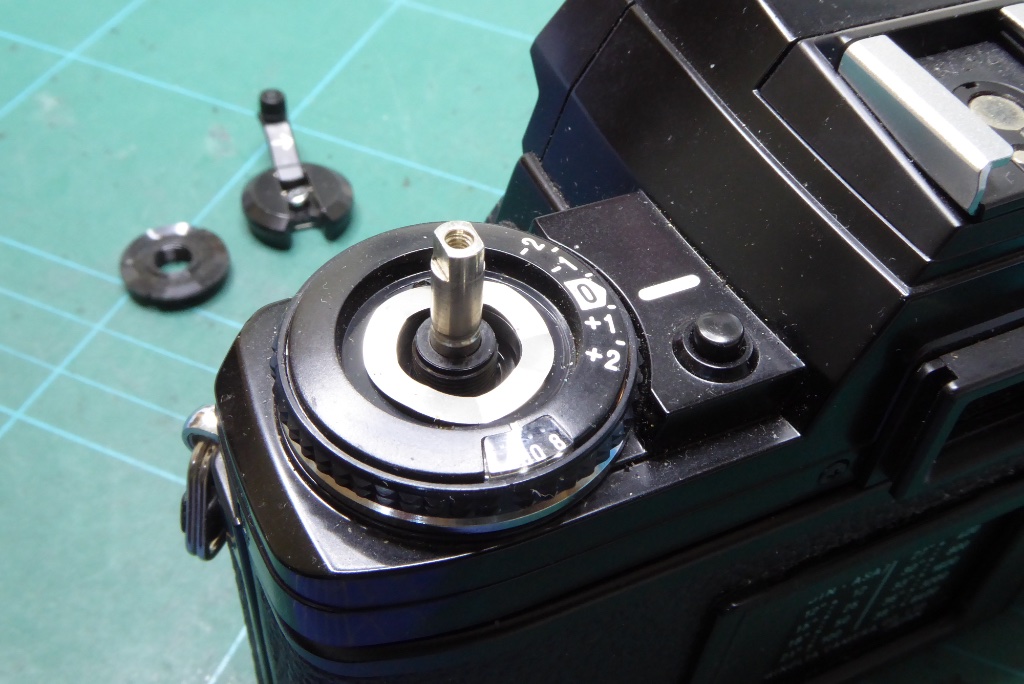
Underneath you will find a washer, remove this.
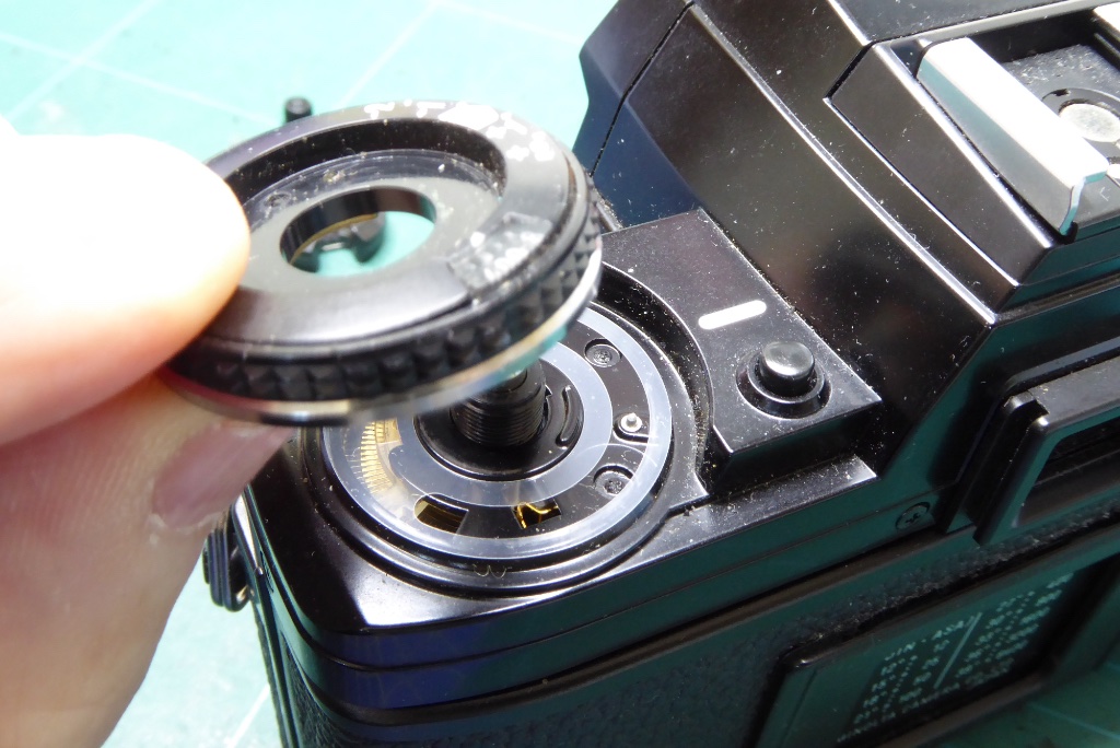
The film speed ISO ring and exposure compensation ring will now simply pull away.
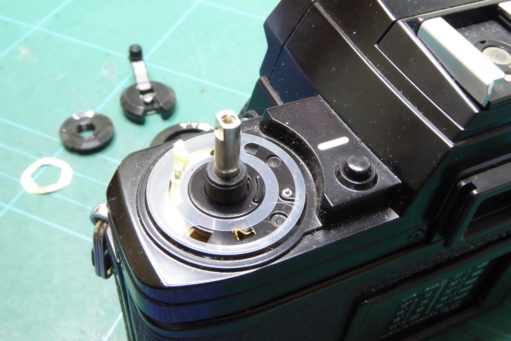
Under the film speed control you will find a thin plastic washer. Note it’s positioning with reference to the slots.
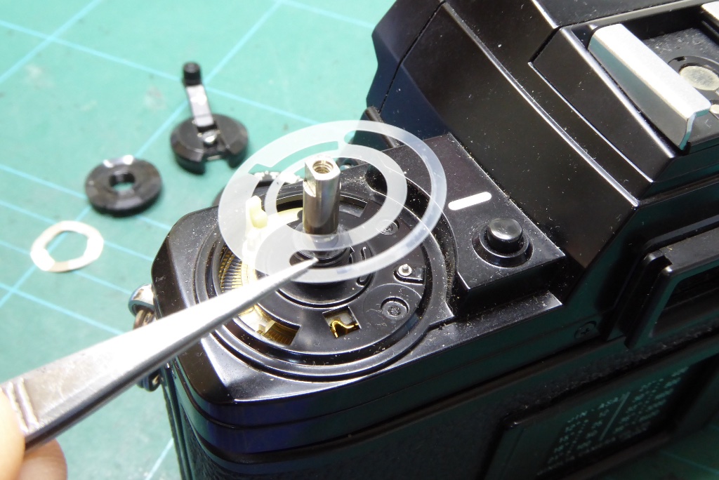
Remove the washer and handle carefully. It is very easy to get this bent or damaged.
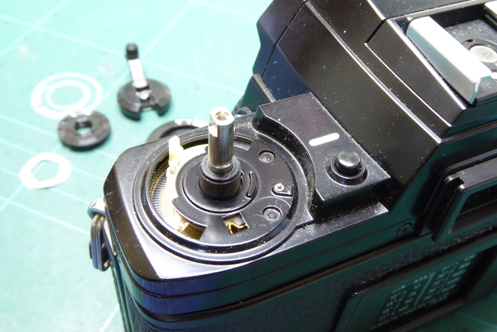
You can now see the levers under the film speed and exposure compensation ring. Make a rough note of where these are located. It will make assembly easier later.
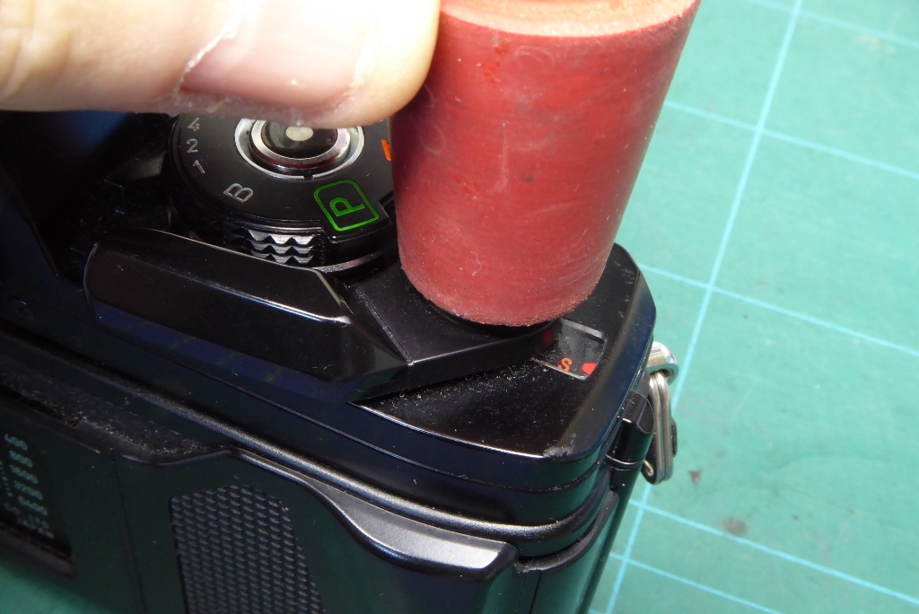
Remove the threaded cap/trim on top of the film advance lever. This is usually not fitted too tight so a rubber bung will usually remove it. It’s a conventional thread.
Here you can see one of my best tools for camera repair in use. Its a wine stopper for a wine fermentation bottle and this tool will remove an awful lot of stuff very easily.
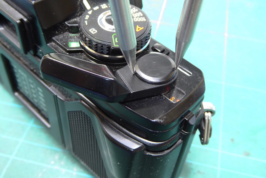
If the threaded cap doesn’t come loose you can either apply a small amount of Isoprop and try after 15 minutes or resort to a spanning wrench.
You do need caution here as the trim can easily be damaged. Normally I would apply some masking tape over the cap to reduce any risk of damage to the trim.
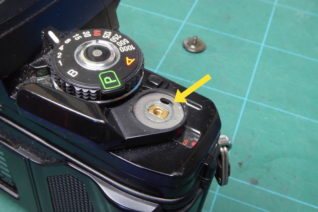
With the threaded cap removed you can see that the advance lever is hooked onto a spring. Some X series do not have the spring and rely instead on a sprung washer. If it’s a sprung washer type the washer will be directly under the film advance. If it has the coil spring gently left the film advance lever up and unhook the spring.
The spring is easily wrecked so do not pull the film advance lever about too much until the spring is unhooked.
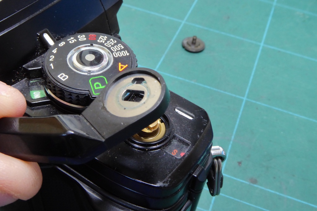
With the spring released the film advance lever will simply pull free.
Be careful as the spring underneath has a tendency to fly off into the void.
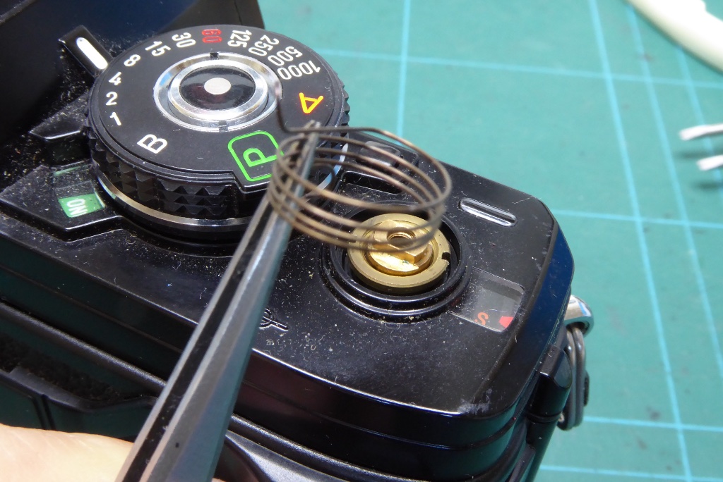
The spring has two hooked ends. One to the film advance lever and one to a slot cut out in the base of the top cover.
Gently ease the spring free and store it safely.
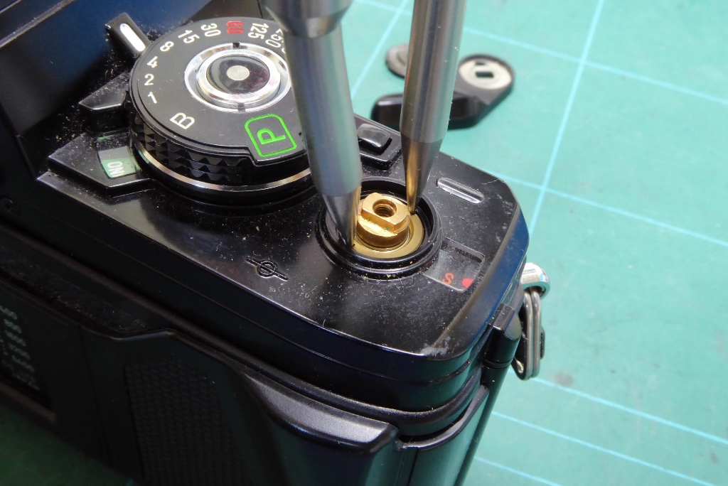
Use a spanning wrench remove the slotted nut.
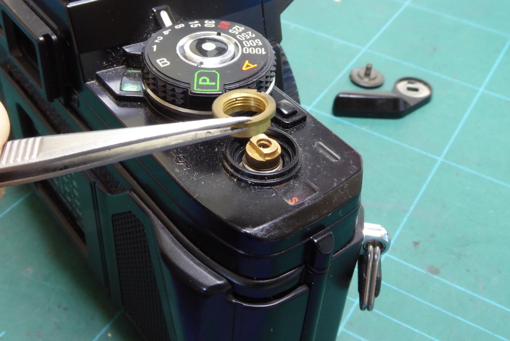
Here’s the nut coming free. Note its orientation.
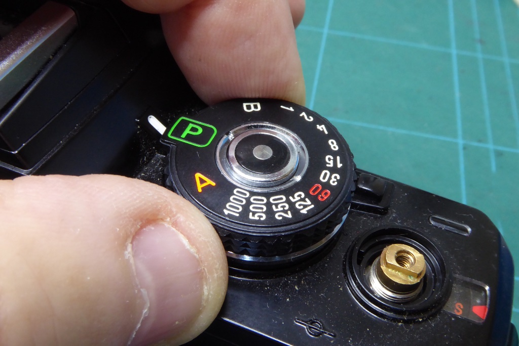
Set the shutter speed dial to Program. This will make life simpler during reassembly and will also allow a test of the camera without complete reassembly later.
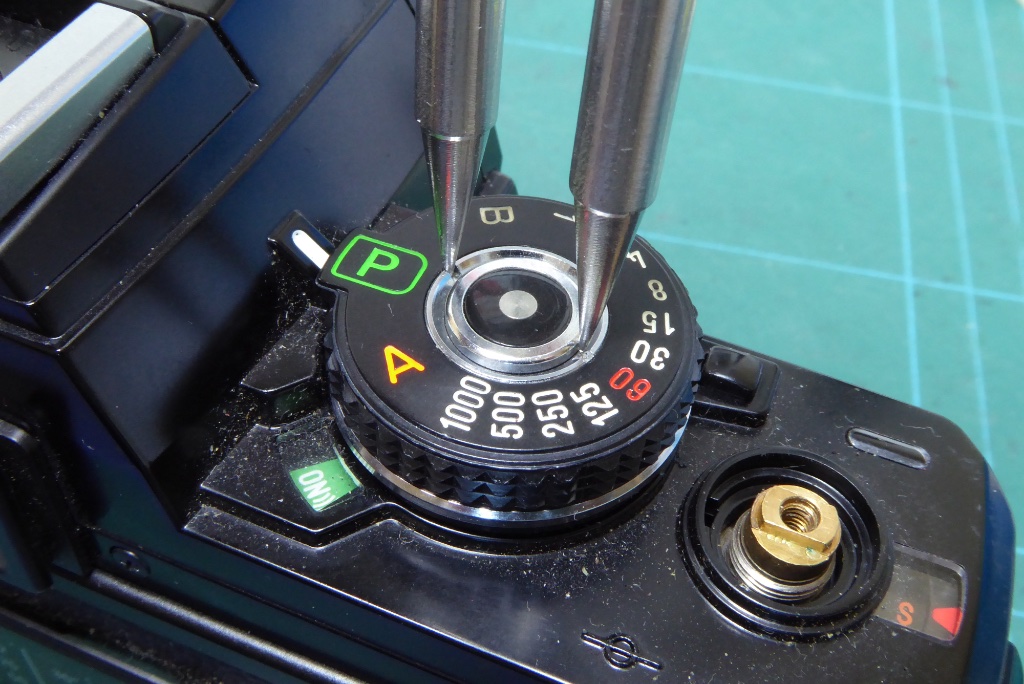
Using a spanning wrench remove the silver trim ring around the shutter release. Caution as the finish is easily damaged.
This ring is usually not very tight.
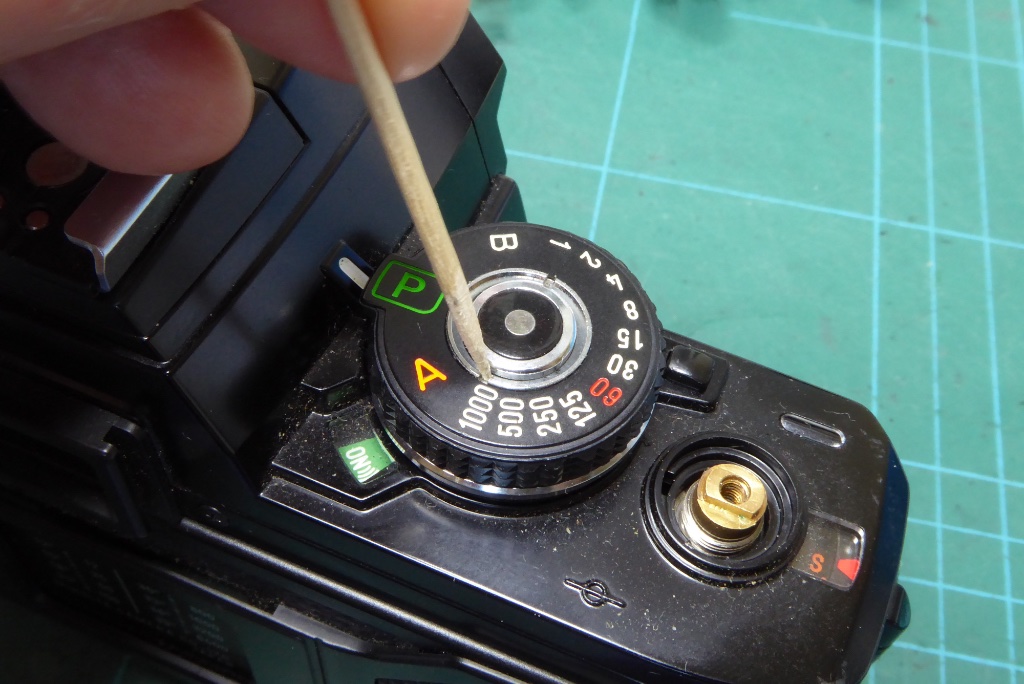
Another camera tool dear to my heart. A cocktail stick. Once items are loose a cocktail stick can be relied on to turn items to remove them and being a soft wood will not mar the finish.
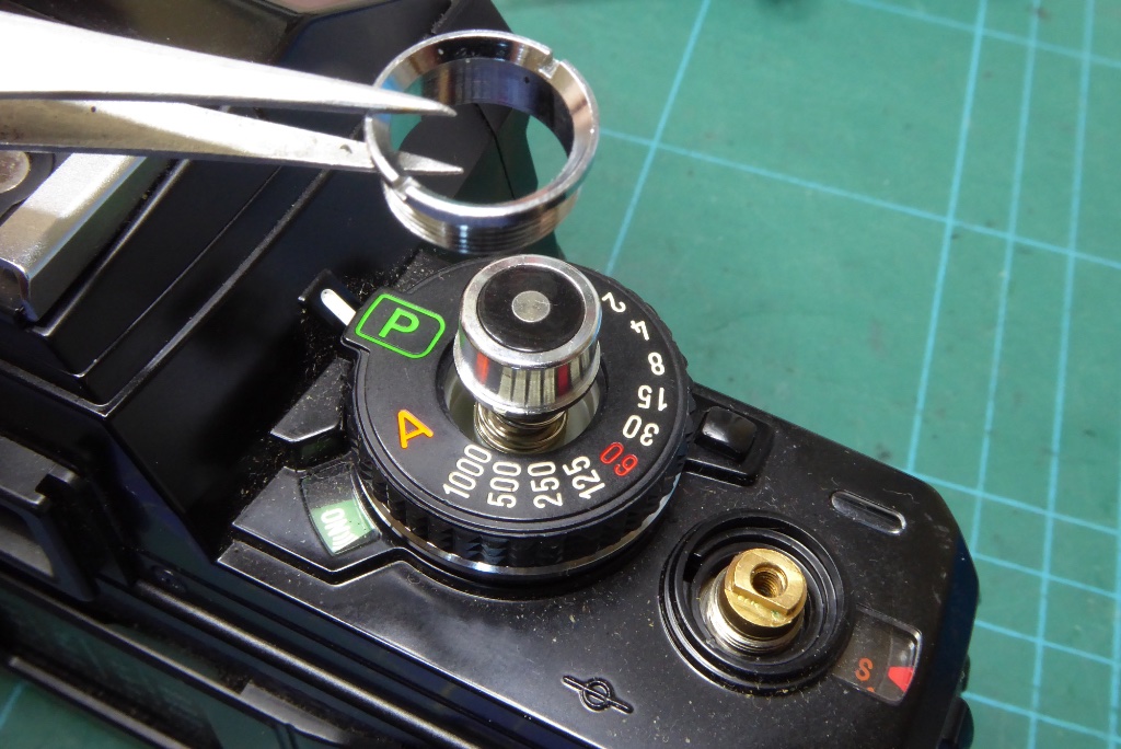
The trim ring is removed. Be careful here when this comes away the shutter button is spring loaded and can easily fly away.
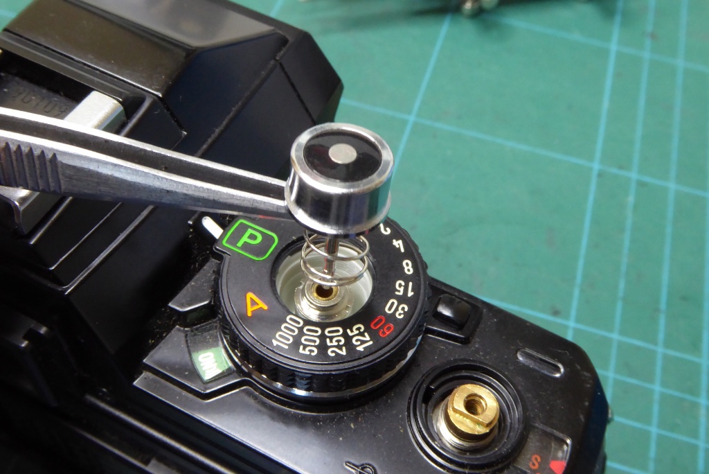
With the trim gone the shutter button and its associated spring will simply pull free.
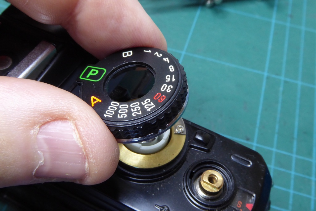
The shutter speed dial can now be lifted off.
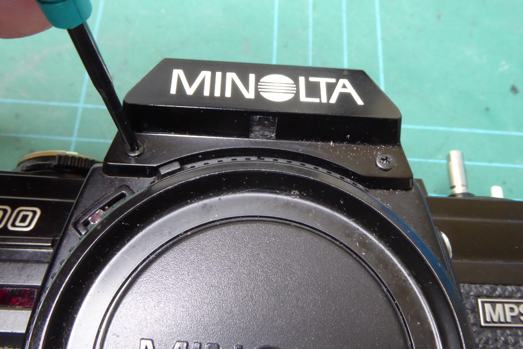
Remove the two screws under the Minolta logo and remove the name plate.
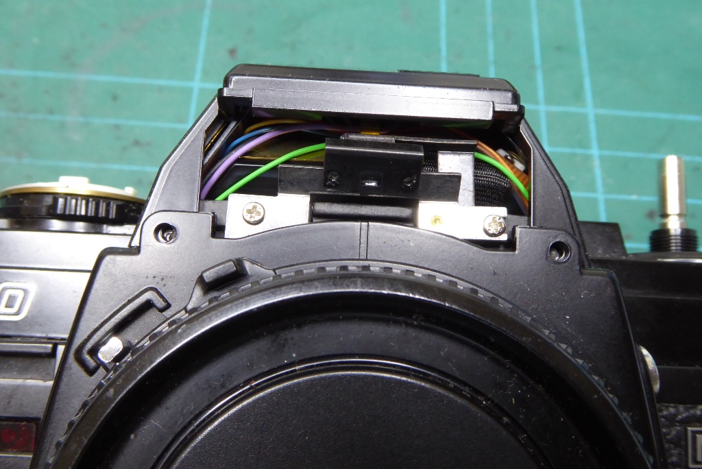
Now you can see the Judas Window arrangement which displays the lens aperture into the viewfinder. Its best not to mess with this as getting the mirror and lens aligned can be a painful experience but if you are missing an aperture mirror (very common on X series) this is where it would be mounted.
All of the screws on the cover are different lengths so best to store them separately or make notes.
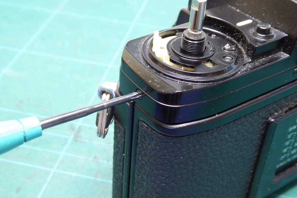
Remove the screw on the left shoulder of the camera.
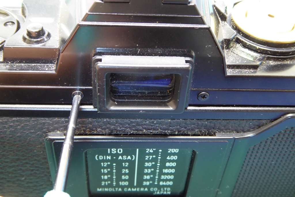
Remove the screws either side of the viewfinder.
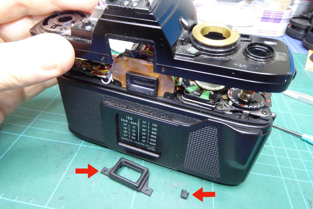
Now carefully lift off the top cover.
As the top cover comes free watch out for the small button which releases the shutter speed dial from Program mode and the viewfinder surround. These are loose once the cover is away.
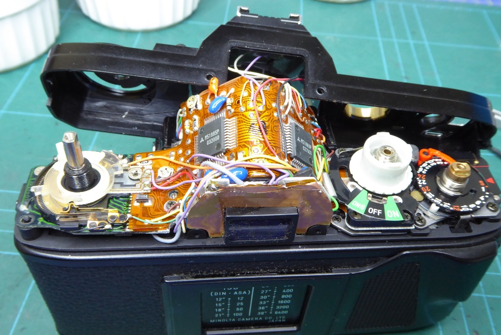
Don’t put any strain on the cover as there are wires attaching the electronics to the hot shoe of the camera and they are relatively fragile. I don’t usually desolder these for a simple capacitor replacement.
Bear in mind you have exposed ICs here so take sensible anti-static precautions.
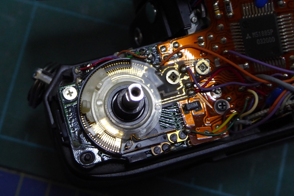
Note the position of the two plastic rings which are under the film speed dial. Remove these and be careful. The inner one contains very fine brushes which act on the copper tracks beneath.
Note that these are sprung and held in place by the film speed dial when assembled. If you want to test the camera prior to assembly you will need to replace these parts and apply a slight pressure on them.
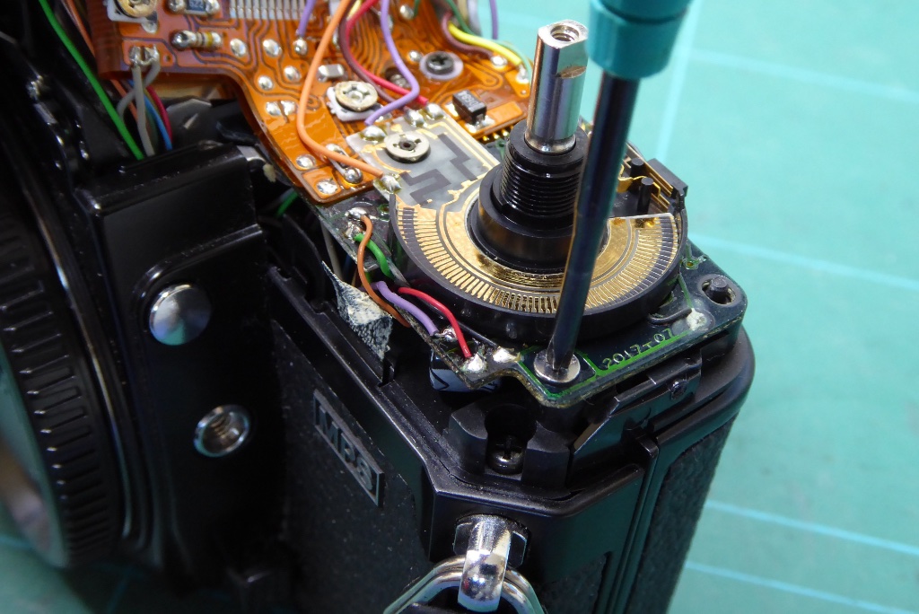
Remove the JIS screw which retains the top circuit board.
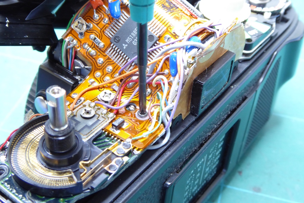
Remove the small JIS screw which retains the flex board and and be sure not to lose the small plastic washer underneath this.
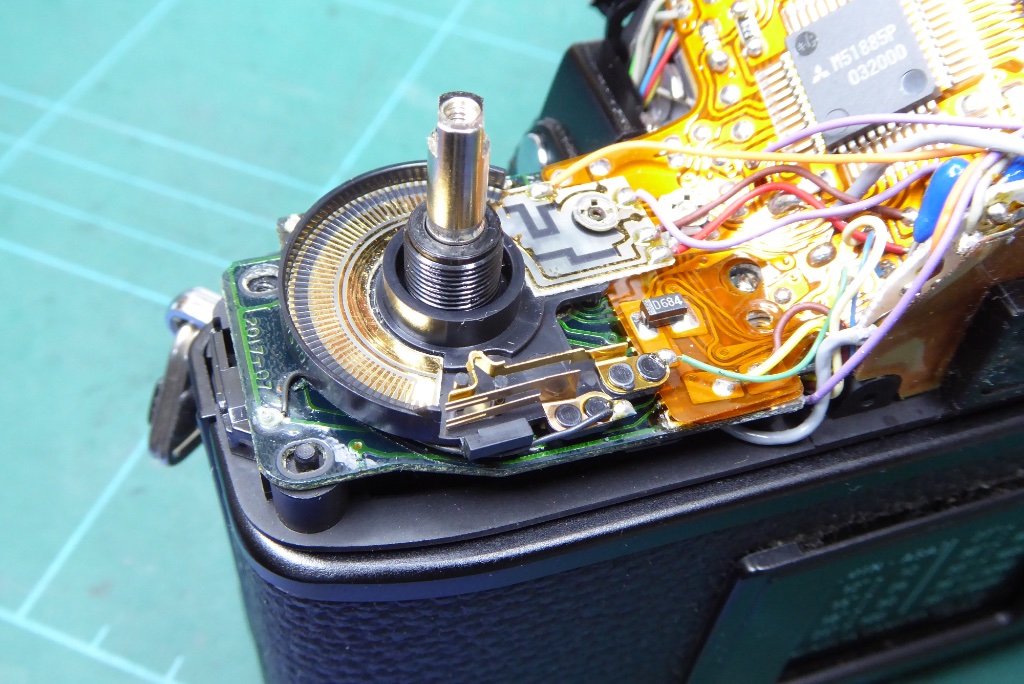
Note the film speed contactor plate and pay attention to the small black wire that runs along its back edge. This is very fragile and during repairs can shear off if not handled very carefully. It can be re-soldered but you don’t’t want to make more work and take more risks.
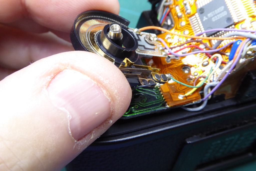
Very carefully ease up the film speed contactor plate. It doesn’t have to go far it just needs to be out of the way.
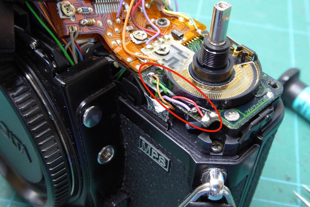
You need to desolder these wires at the front of the circuit board. There is a small sticky tape that holds these in place. Carefully peel the tape back and desolder these.
This is why the contactor plate was lifted in the previous step – its plastic and its very easy for it to get clipped with the soldering iron.
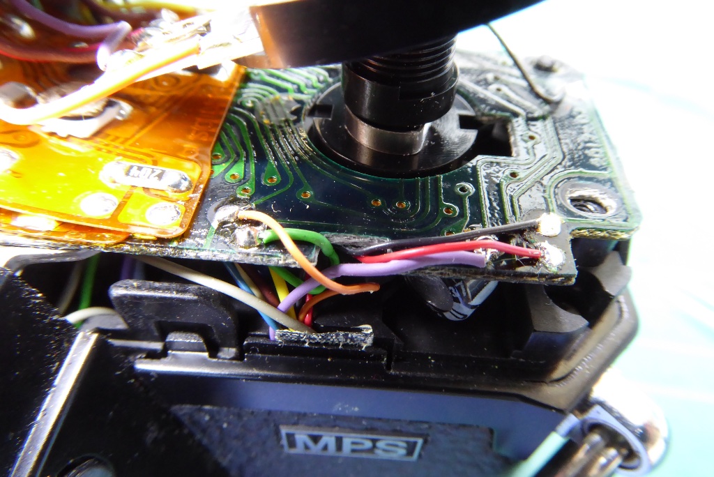
Heres the wires again as a reference.
It is worth making your own notes though as I have seen some Minoltas where the wiring colours were different.
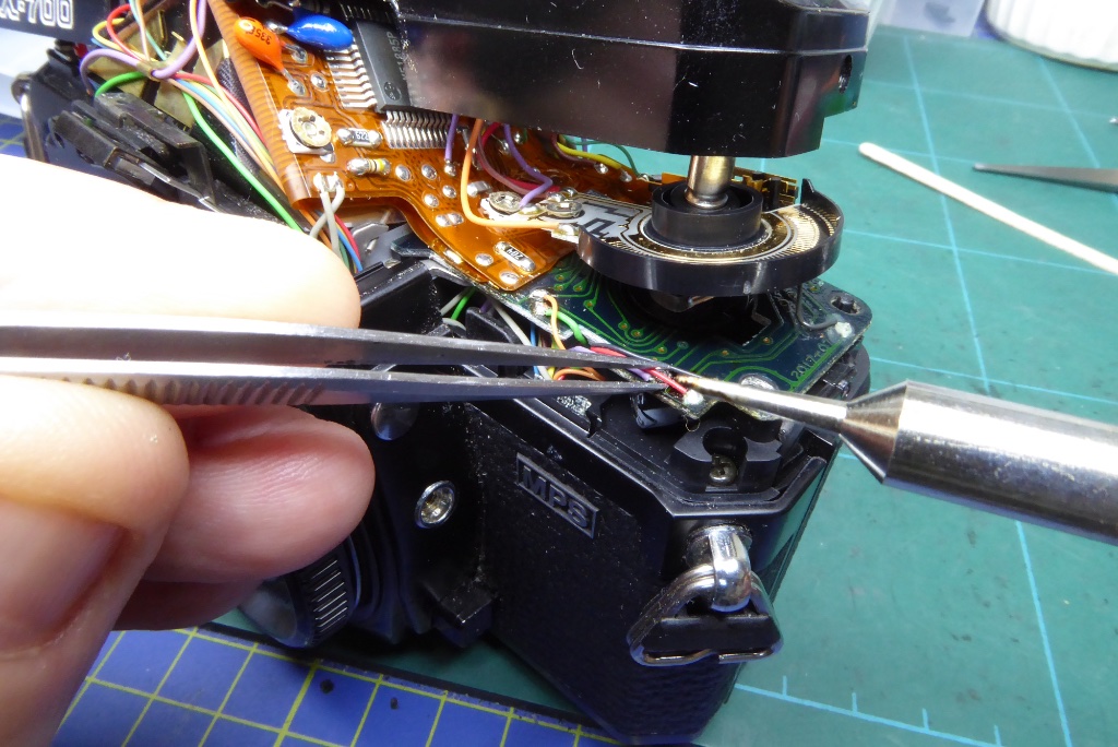
Carefully desolder the wires from the front edge of the circuit board.
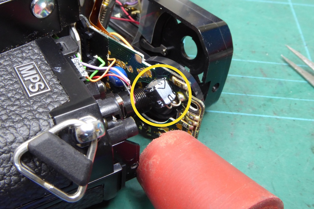
Now you can very gently lift the circuit board. It may stick a bit close to the prism. Do not apply force but a gentle jiggle will free it.
Close to the prism the circuit board has LEDs which fit into a plastic mounting which relays the LEDs to the viewfinder. Its like a small multi connector plug and can sometimes need a small amount of jiggling to free it.
Now we can see the aperture control capacitor. Note the orientation of its grey/white stripe indicating its (-) leg.
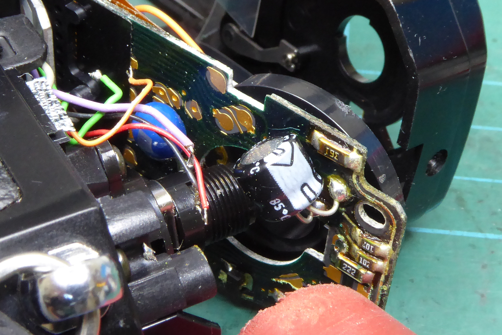
Carefully pull the circuit board back but do not apply pressure or lever it around. The PCB to flexboard tracks and joins are very fragile.
To get a picture I am using a rubber bung to hold the circuit board open a bit to give you a view of the aperture control capacitor. I also use this to keep the board opened while desoldering the capacitor and fitting the replacement. As with the other capacitor it is easiest to clip its leads to remove it and then desolder the remaining part of the leads.
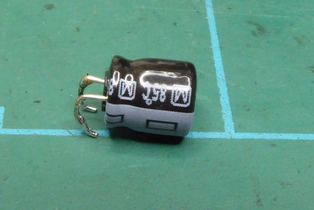
Here’s a replacement ready to go. Its legs have already been formed into the right shape and the leads have been tinned. You can also see its coloured stripe indicating its (-) negative leg.
Placement of this Minolta X-700 capacitor is quite critical as it can easily foul on other parts so you need the utmost care in getting its placement perfect.
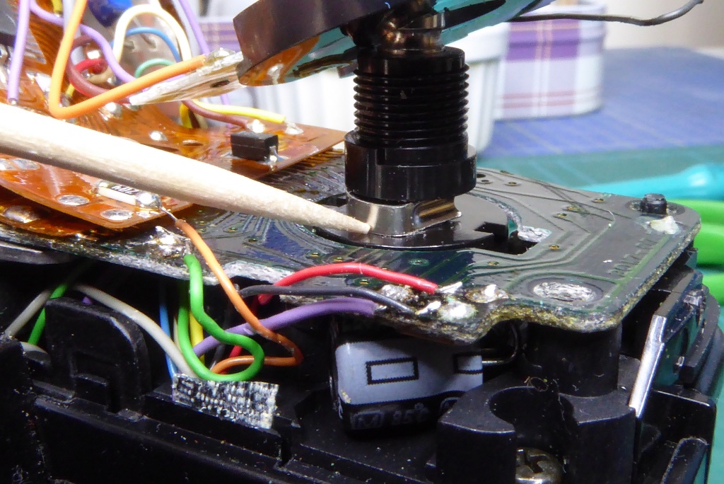
With the new capacitor in place you now need to solder the leads at the front edge of the board.
Note the silver coloured clip around the the film spool housing and make sure this pushed home otherwise it will not allow the contactor plate to be replaced easily.
Note also how close the capacitor is to the camera edge and internal mouldings. This is why placement is quite critical
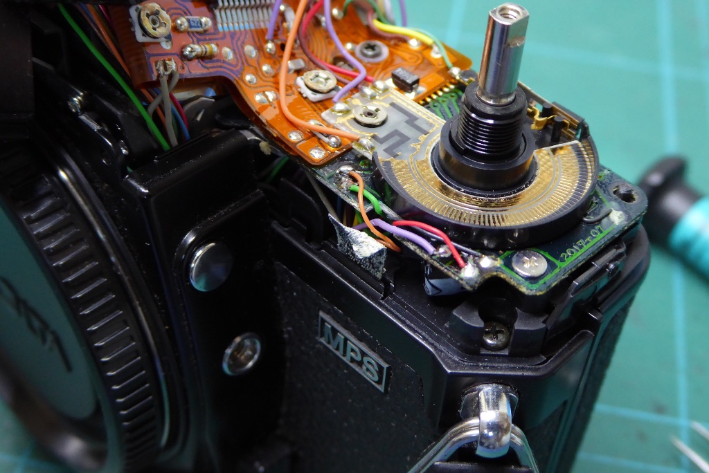
With the leads re-soldered push the contactor plate back into position. Note it is keyed so will only fit in one position.
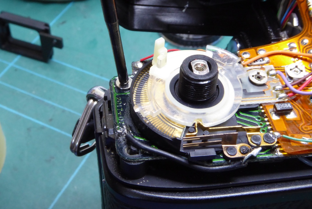
Make sure the circuit board is seated correctly with its LED plug block near the prism reseated.
Replace the JIS circuit board retainer screw.
Replace the film speed/exposure compensation rings and check that the black wire seen here at the back of the contactor plate is still connected.
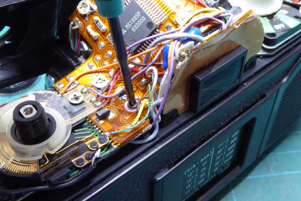
Now replace the flex board retainer with its plastic washer.
If you wish to run a test now before replacing the top cover; replace the batteries, fit a lens and set it to f16, put the advance ever loosely on just so you can wind the camera on and put the shutter button into the camera, apply slight pressure to the film speed/exposure compensation rings to put them in contact with the contactor plate and press the shutter button. If all is well the camera will trip the shutter.
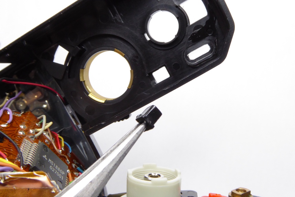
Replace the shutter speed lock button into its position…
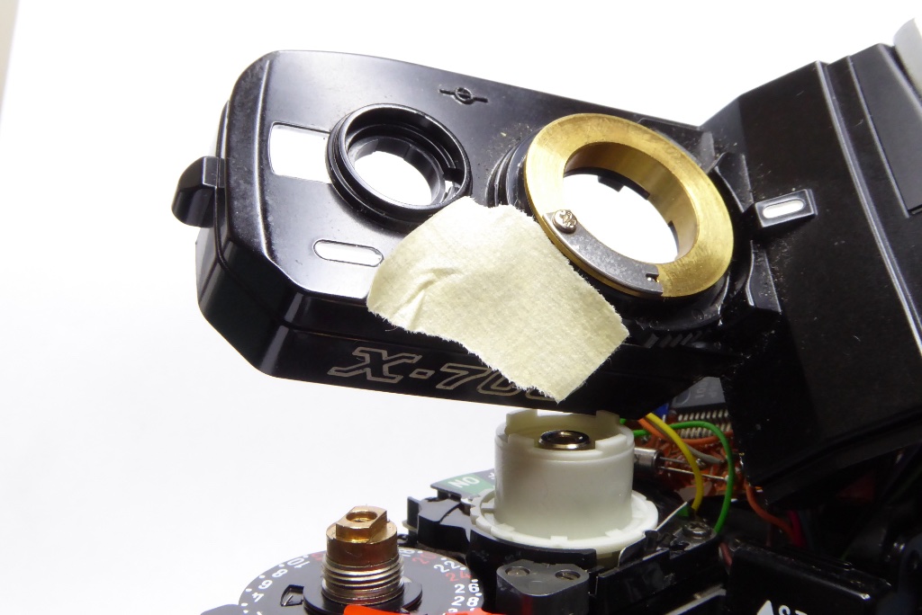
…and use a bit of low tack tape on its top to hold it in place while you replace the cover.
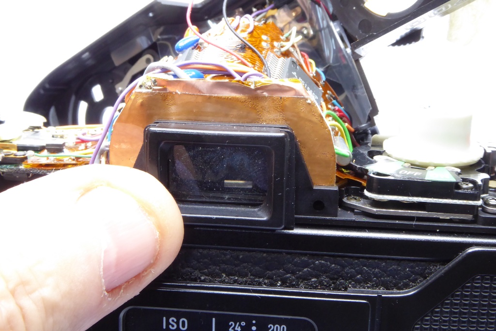
Replace the viewfinder surround and gently ease the top cover back onto the camera. Make sure you don’t pinch any leads while replacing the cover.
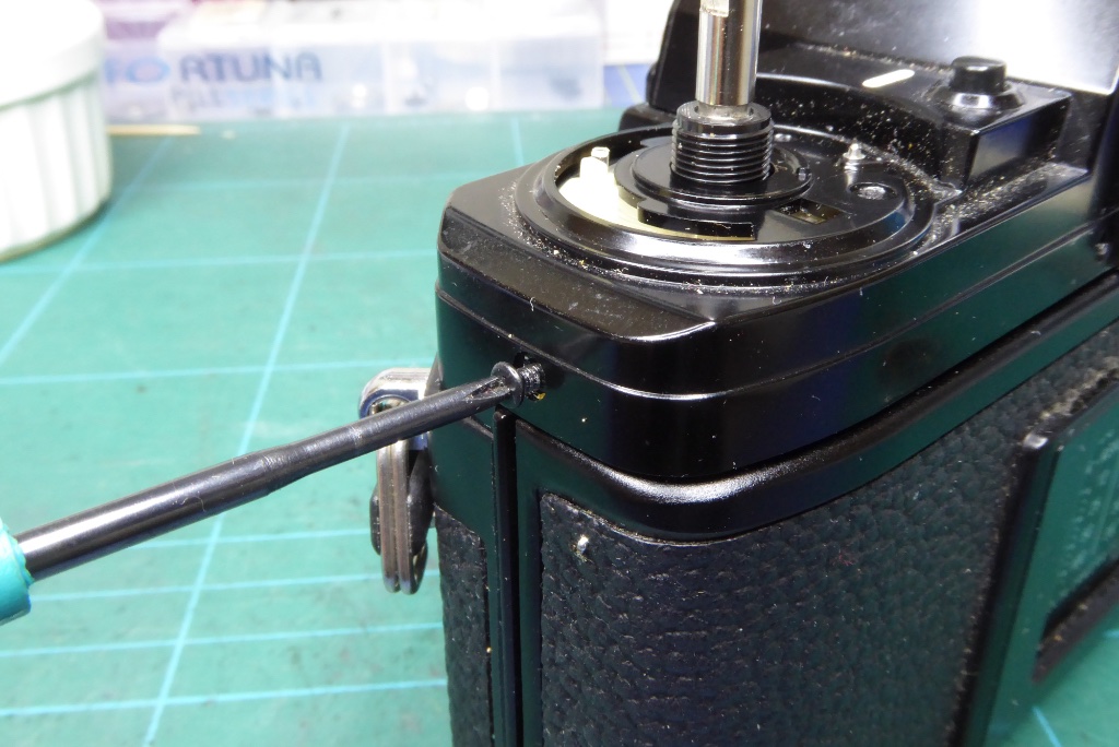
Refit the screw on the left shoulder of the camera.
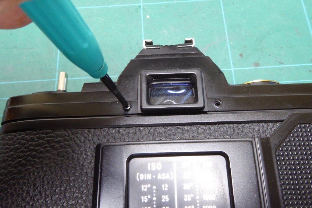
Refit the screws either side of the viewfinder.
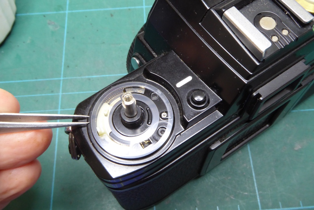
Replace the plastic washer under the film speed ring.
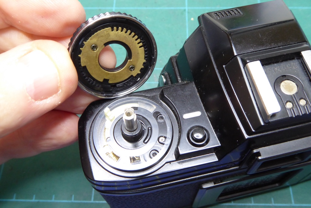
Refit the film speed/exposure compensation ring. Note the cut outs in the ring and align these with the two plastic levers which you can push into their original position from your notes earlier.
It’s easiest to replace the ring and ‘feel’ for when the levers are located. If it doesn’t feel right then it probably isn’t. Do not force things.
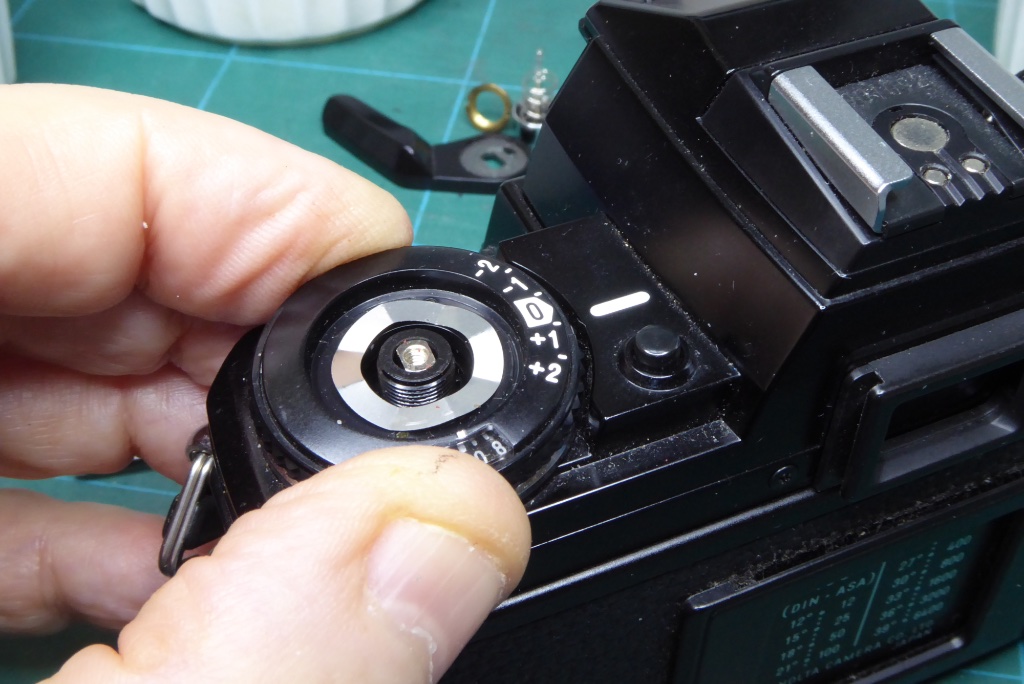
You should be able to feel the film speed ring is right without putting any of the retaining fittings on.
By gently pressing its down and pressing the exposure compensation button you should feel it click into place correctly.
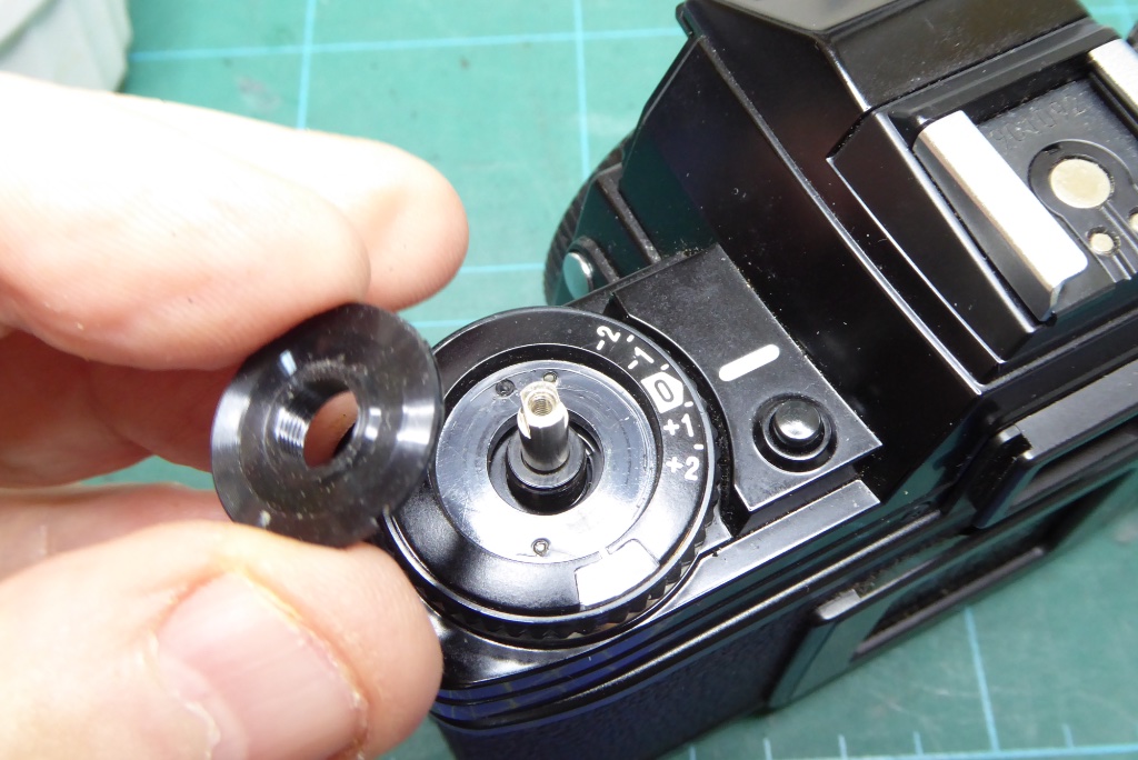
If all seems well fit the sprung silver washer (missing in this photograph) and the replace the slotted retaining ring.
Loosely tighten down and check that the ASA dial can move from lowest to highest ASA. Set it at around ASA 400 and check the exposure compensation can also move between -2 and +2
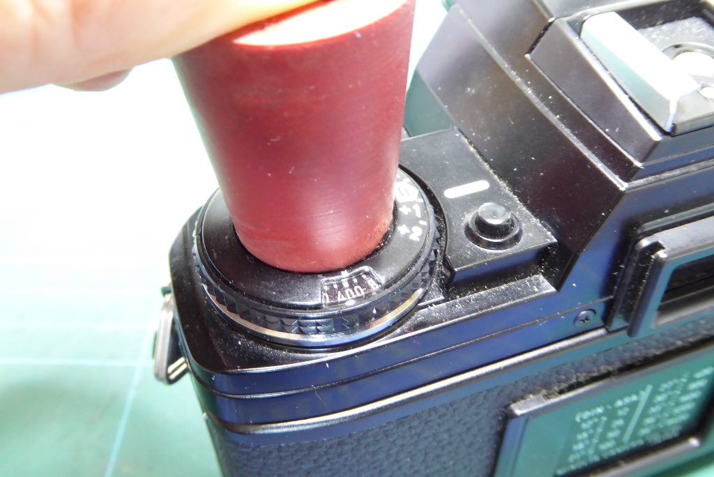
Do NOT over tighten the ASA retaining ring – you will run the risk of cracking the film spool guide plus if its over-tight and it will make the exposure compensation ring very tight to turn.
I normally use a rubber bung, tighten down gently until it impacts the sprung washer and then apply 1/8th to 1/4 turn. The sprung washer acts to stop it coming loose so it doesn’t need to be very tight.
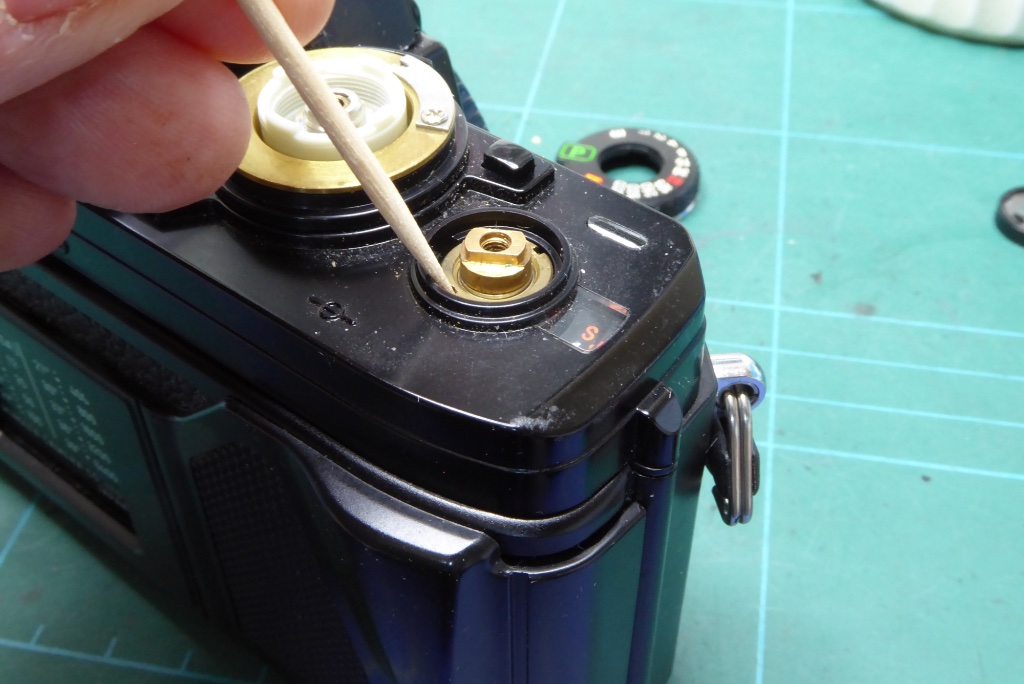
Replace the slotted nut under the film advance lever.
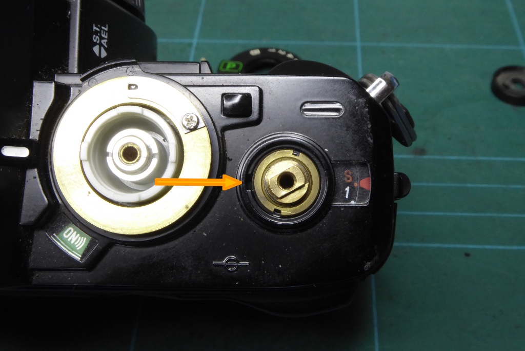
Note the slot where one end of the film advance spring hooks on.
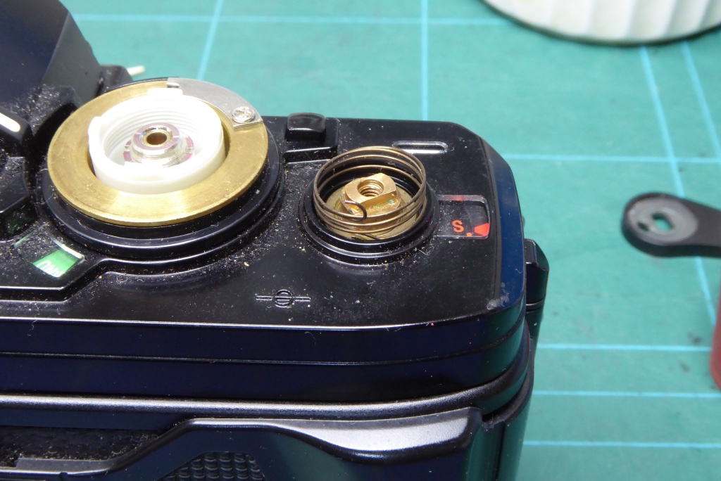
Hook one end of the spring into the slot.
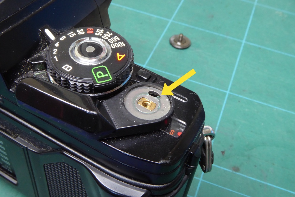
Hook the other end of the spring onto the advance lever….
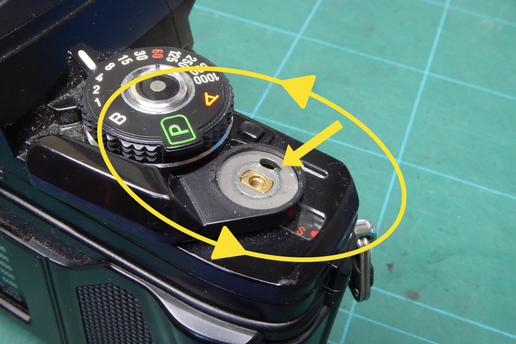
…you need to tension the spring so with the spring hooked on you need to rotate the entire film advance lever round in an imaginary circle ABOVE the spindle and then fit it onto the spindle while making sure the spring does not get trapped or run under the advance lever. This is tricky and its easiest if you don’t have the shutter speed dial in the way. You need one complete turn of the spring before fitting the advance lever down onto its spindle.
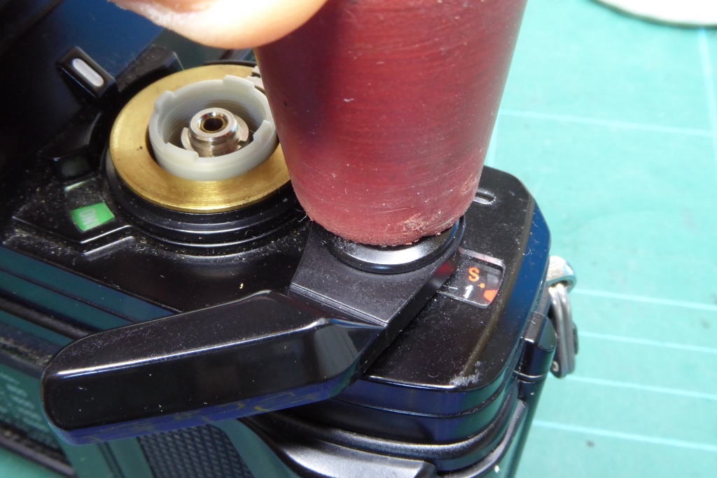
Replace the threaded trim and tighten down with a rubber bung. Do not apply too much pressure as you can shear the threaded part away from the cap quite easily..this is best done with a rubber bung rather than a lens spanner. Its too easy to end up shearing the threaded part off with a lens spanner.
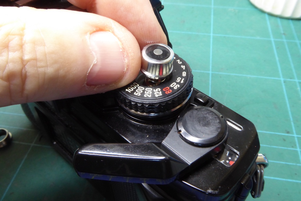
Replace the shutter speed dial and shutter button and then…
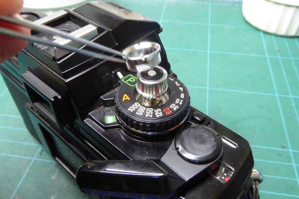
Replace the trim/retainer. Tighten this down to not much more than finger tight.
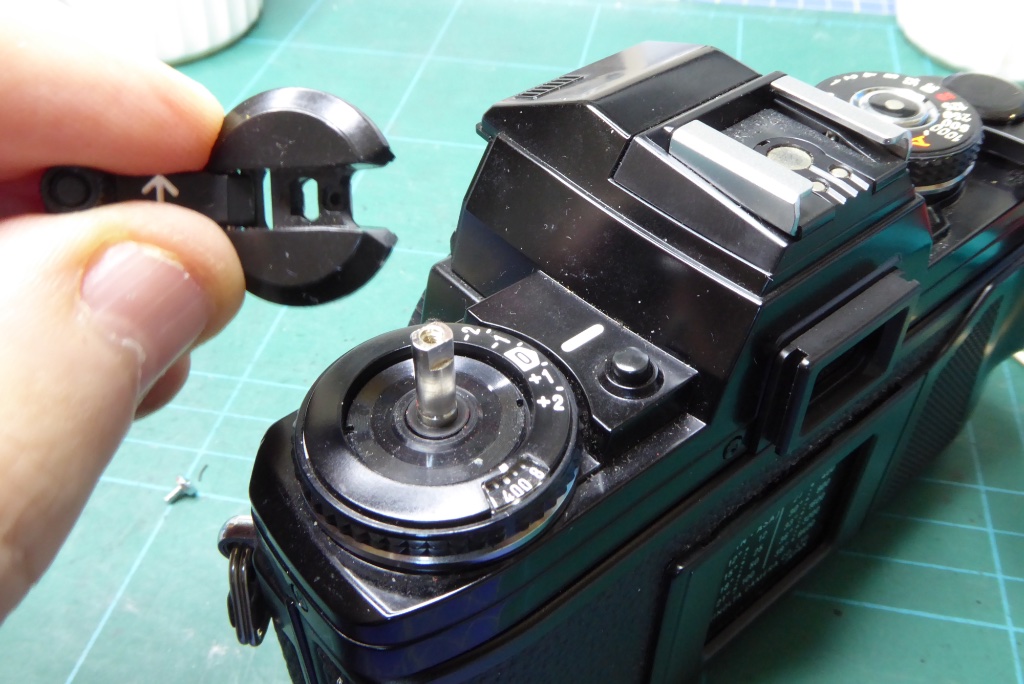
Note the rewind capstan has a keyed shape and locate this to the top of the film spool spindle.
Do not allow the spindle to be pressed down into the camera so either grip it with some pliers or wrap some tape round it to stop it being pushed down.
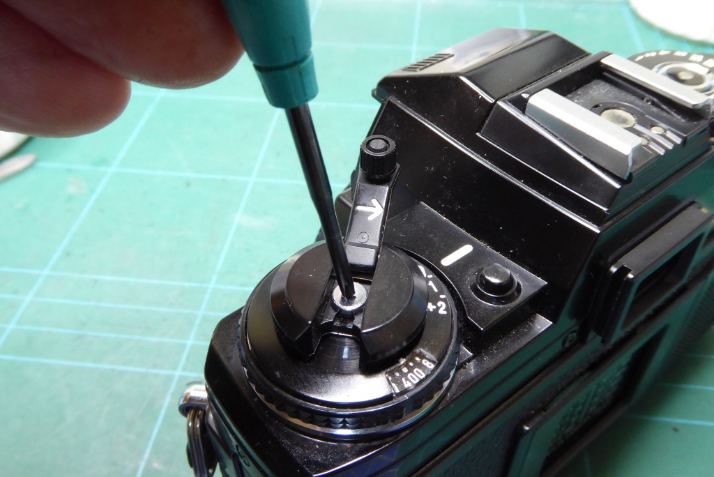
Replace the JIS screw on top of the rewind capstan.
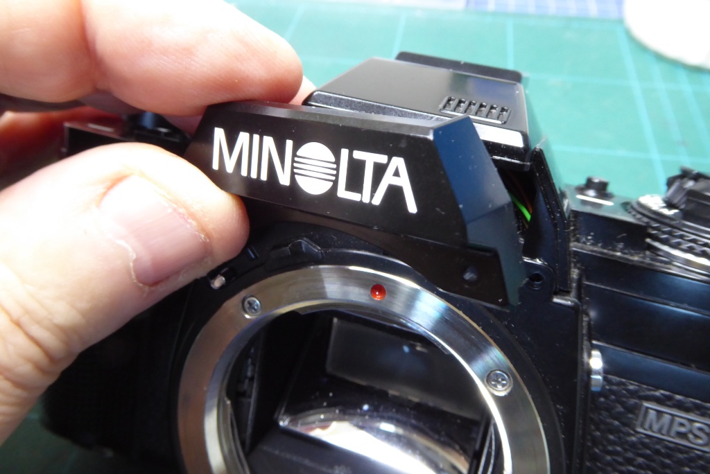
Now replace the Minolta name plate…
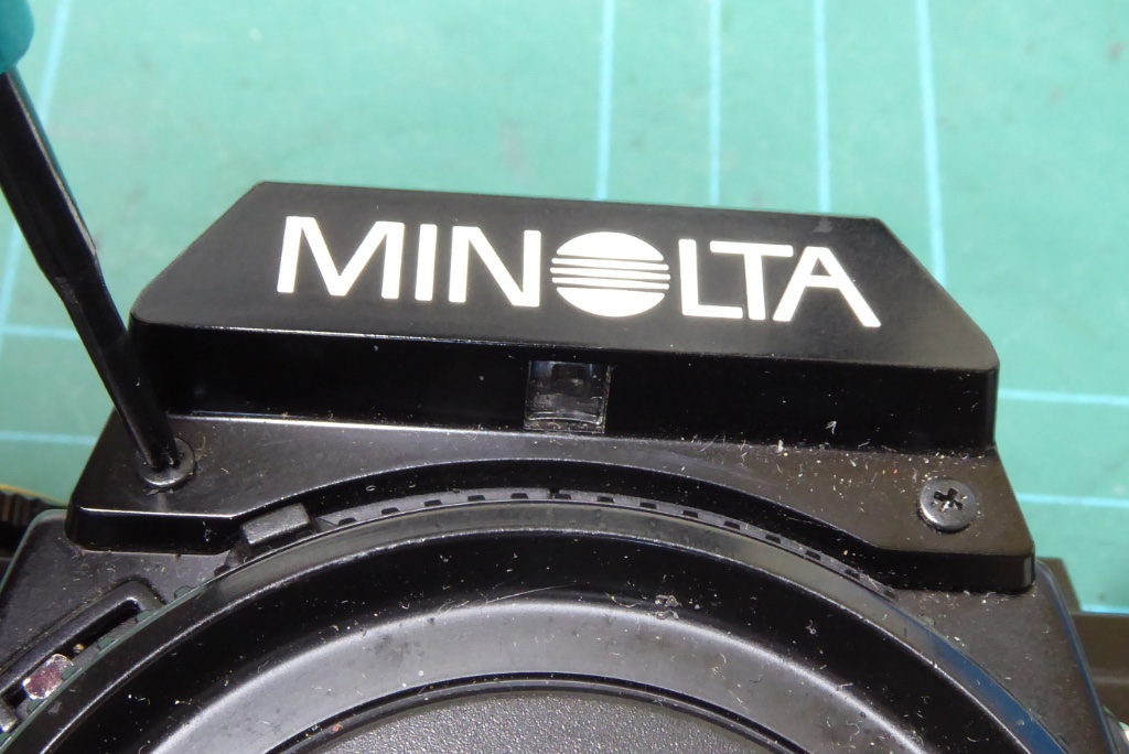
…replace the two screws either side of the name plate.
Give the camera a check to make sure all functions are operating correctly and pay attention to making sure all viewfinder LEDS are showing.
If you cracked any circuit tracks you may find the ‘P’ or ‘A’ indicators are missing.
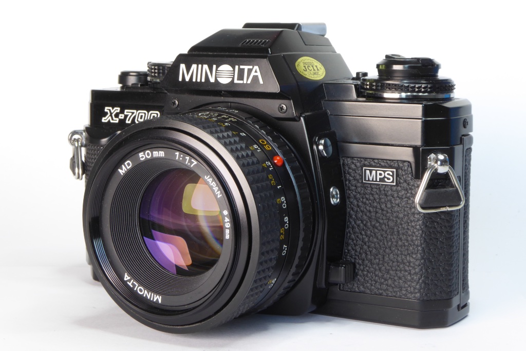
If all has gone well with your Minolta X-700 capacitor replacement you now have a fully working camera.
Treat yourself to your favourite beverage and get ready to get some great pictures.
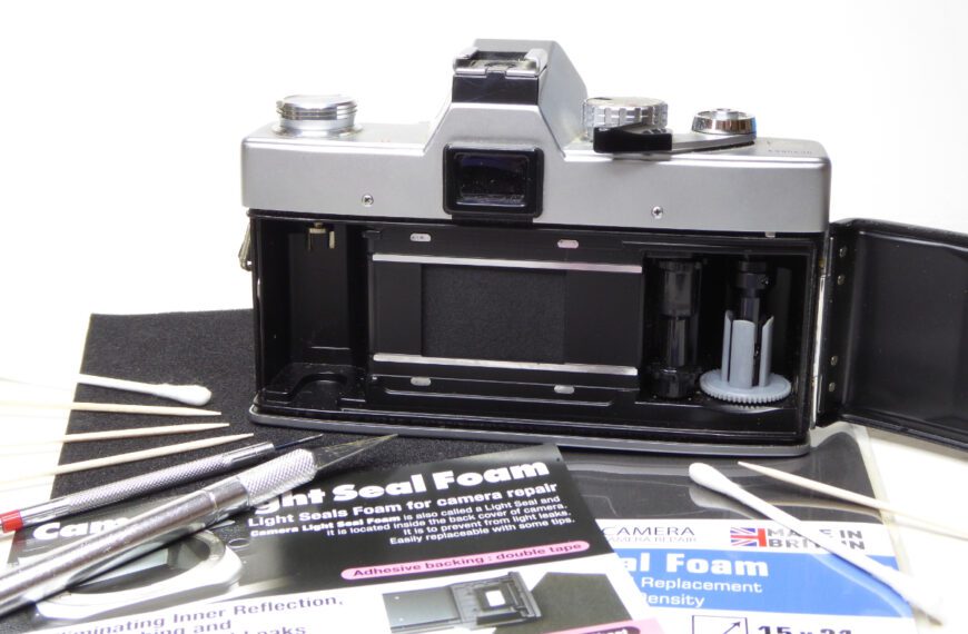
You may want to treat your newly repaired camera to some new light seals so check out the guide HERE for light seal replacement on the X-700.
Further Reading

Mel is one of the driving forces behind High 5 Cameras and writes all our articles.
Starting serious photography back in 1972. Over the years she got to shoot film with most of the major brands in 35mm and large format as both a studio photographer and content provider for websites in the early life of the web. These days she is rediscovering photography and has become the GOTO person for knowledge on camera repair advice.


Nice job Mel, if a novice can’t repair and X-700 with bad caps from this video than they shouldn’t be trying to do repairs.
Thanks James,
As ever I would always recommend those wanting to learn repairs should be looking at learncamerarepair.com for information and not trust You Tube videos which are often very poor.
My camera has the tell tale symptoms and I am going to attempt repair myself. Do you find that if one capacitor goes bad they all do? I feel pretty confident about the bottom but I had issues on the top on a test run camera. Thanks.
On an X-700 you can pretty well bet if the bottom capacitor is gone the top one wont be far behind. It is a tricky repair but nowhere near as bad as dealing with many classic cameras. What problems did you have?
Fantastic! The X-700 was the first camera I owned back in college – but long gone many upgrades ago. I always had a soft spot for it, though, so recently, I bought a non-working one in great cosmetic shape with the intention of having it repaired. I was aware of the capacitor issue and requested the repair tech I’d found to replace both; he did so, declared it working, and sent it back. What he failed to do was check it thoroughly, as I discovered that, indeed, the shutter fired, but only a dozen or so times, and then it went dead. The following day, it would work again, fire approximately the same number of times, and then die. The same thing every day for a few days. Then I discovered your article, the section in which you reveal the tip of bypassing the circuit board and directly connecting the two yellow wires. This was something I could do with my own tools, so fingers crossed I gave it a go. Astonishingly it worked like a charm! I’d be very interested to know why this seemingly obscure repair works. I’ve never come across it any of the extensive number of videos and articles I’d watched/read trying to diagnose the problem. Thanks for your work here!
Mel cant claim the credit here for this fix which rightly belongs to James Holman who is a very expert repair professional. James discovered this with extensive reading of the circuit diagrams but even he isn’t 100% sure why this works. It doesn’t really make any sense at all but it DOES work. We routinely apply this to any X-700 we repair as a matter of course.
Your repair tech would most likely have been unaware of this fix which is quite obscure. We are glad our guide could help you.
The issue you had with your repair is exactly why we never sell a camera that hasn’t had pretty extensive testing. Our regime is always to CLA the camera completely. Test fire it and then let it sit getting a few shots each day as a test fire. At the end of around 30 days we retest to make sure its speeds and settings are still correct and then we load it with film. It then gets used as our primary carry camera for a roll of film which is processed. Assuming the film results are good it is then test fired periodically while we wait for it to sell. Prior to sale the camera is retested and checked on our professional test gear. Someone asked Mel recently why we bother to film test when the cameras are checked on professional gear. You have your answer with your repair. Old cameras can sometimes work perfectly on a bench and a bit less so out in the real world.
Check out our latest article ‘Being There’ which is the first of a series Mel is writing to hopefully coax people into getting the best shots they can.
Best regards and wishing you a happy Christmas and New Year.
Thank you do you have one for fixing the film counter?
We dont have a guide and I am not 100% sure what your issue is but it is most likely either that the frame counter wont advance which will be down to a spring becoming disconnected or that the counter will not reset properly which is down to the small stud on the counter dial being broken.
Both are relatively easy repairs and you should be able to find a resource online for these. We might do an article on this in the future covering this as it’s a quite common fault.
Mel
Hey there, I was wondering if the volt on the capacitator matters that much. I’m not finding many capacitor replacements that are 4v. But I am finding 6.3v, 10v, etc. Would using a 220uf 6.3v capacitor work?
The voltages, so long as its greater than 4v is not an issue but size of the capacitor is. The top capacitor in an X-700 is quite tiny as there is quite a lot of other hardware crammed into the small space.
The capacitors are available in our online store.
Hi, that’s a great guide, thank you! I’m trying to decide whether I should get myself an X-300 or X-700, but I’m rather daunted by the prospect of having to replace the top capacitor. As I’m not really interested in the Program mode, I wonder if the X-700 would still function in other modes if only the bottom capacitor is replaced? Thank you!
Without the upper capacitor operating the X-700 will not run. It relies on this for it aperture control. You could consider the X-500. There are fewer of them around but it basically does everything the X-700 can do but with no Program mode. The X-300 is also very capable and often available at a much lower cost.
Avoid the XG-M – it has four capacitors to worry about and three of them are a real headache as they are on the top PCB and its quite an awkward camera prone to a fair few issues. If you can find a serviced one thats had a capacitor change the XG-M is very nice but we serviced and repaired a fair few of them and they are quite a bit of work to do and few people will pay for a full service on one.
We have an article on the X series on the site you may find interesting.
Thanks, that’s enormously helpful! I’ll try to source out an X-300, and hopeful it won’t need a new capacitor to begin with, at least for some time.
You are more than welcome
Why not check out some we have for sale. Fully CLA serviced and film tested.
We have some on sale as we speak
https://high5cameras.com/on-sale/
Mel
Thanks, Mel, I’ll take a look!
Thank you! Best tutorial I’ve ever went through! I didn’t have the ALEC capacitors near me but I found some surface mount tantalum capacitors that worked perfectly for me! A bit harder to solder the surface mount capacitors but they do their jobs better than the capacitors that were in the camera 😉
Thank you and obviously glad to be able to help you out. Keep an eye on our articles as we put new ones up every month.